How To Design TPE Parts For Injection Molding
Last update on Apr 1, 2008| Keyword abstract: thermoplastic elastomers, TPEs, design, injection molding, TPVs, SBCs, TPUs, COPEs, TPO, mold filling, shrinkage, warping, mechanics, industrial design, weld line, air entrapment, draft angles, ejection, wall thickness, ribs, bosses | |
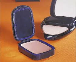
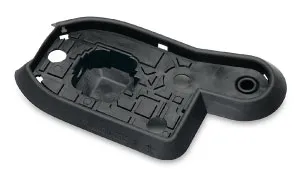
IIR/PP TPV Example Cosmetic Case Seal Designed for Function, Appearance and Injection Molding |
Identifying the correct TPE type and grade to use is the first step to successfully design a part. The general breakdown of TPEs used for injection molding into TPE parts is into the broad categories of block copolymers, rubber-plastic blends and thermoplastic vulcanizates. Block copolymer include styrene block copolymers (SBCs, SBS, SEBS, SIS), thermoplastic urethanes (TPUs) and copolyester block copolymers (COPE) as some of the major ones. Rubber : plastic blends of commercial significance include the EPDM rubber : polypropylene (PP) blends (i.e. thermoplastic olefin blends, TPOs) and the nitrile rubber (NBR) : polyvinylchloride (PVC) blends. Thermoplastic vulcanizates consist of a cross-linked rubber phase dispersed in a continuous thermoplastic phase and these include the rubber : plastic combinations: EPDM : PP (EPDM/PP TPV), Butyl rubber : PP (IIR/PP TPV, Nitrile rubber : PP (NBR/PP TPV), Ethylene acrylate rubber : PET polyester (or nylon) (AEM TPV) and silicone rubber : nylon (or PET) (TPSiV). This step consists of the steps:
- Material selection
- Driving environmental conditions identified
- Material performance extremes contrasted to requirements
- Material selection validated
- Part design process accounts for characteristics of selected TPE
Consult a good TPE information source to guide this part of the process.
Designing a TPE part for injection molding will include the process steps common for developing a successful part design.The broad breakdown of the design process is into the following steps:
- Part Aesthetics and Differentiation
- Industrial design
- Overall design validated with feedback
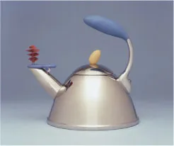
Kitchenware EPDM/PP TPV Industrial Design Example |
- Criteria established for part function
- Design to meet functions
- Validate design functions
- Injection molding process design factors
- Mold design capabilities and limits accounted for
- Moldfilling conducted on part design
- Process economics and quality capabilities optimized
- Demolding, assembly and automation optimized
The focus here will be on this last portion of the design process where the injection molding process design factors must be accounted for when designing details for the TPE parts.
The TPE part designed for injection molding needs to incorporate design features that work within the mold limitations, processing effects and economics associated with this process. Many issues required for rigid thermoplastics are roughly equivalent with TPEs. But since TPEs are softer and often quite flexible there are some factors that can be more forgiving and others that are less forgiving. These differences include:
- Softer TPEs require large ejector pins
- TPEs have higher surface friction with more flexible material
- Deep textures are hard to eject and require larger draft angles, but may not be as difficult as for a rigid thermoplastic
- Short cooling times cause deformation, ejector pin marks since the softer TPE is easier to deform until fully cooled
- Ribs require a slightly higher draft angle
- Poor release draft angles can cause a vacuum and part collapse during ejection can occur easier in TPEs
- Runner systems are very flexible and can hang during ejection
- Flexible TPEs can often be readily ejected even with significant undercuts
- Avoids need for more elaborate mold splits or collapsible cores
- Allows for air ejection in some cases
- For overmolding use softer TPE over rigid plastic substrate to avoid deforming the softer TPE portion, and the TPE grade must be compatible to bond to the plastic
- Gussets to support bosses may be less problematic in the softer TPEs, where the high stress concentration points flex instead of cracking as in rigid thermoplastics
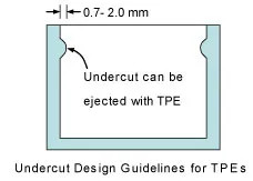
Undercut Design Guidelines for TPEs |
There are some processing options that may be limited to the specific TPE and grade chosen so the raw material supplier should be consulted.
The mold design process and process parameters are also important areas to developing a TPE part design. Mold filling analysis and mold design techniques are used to establish the best gate method and location. The runner system style is also a factor in the gating decisions. Molding cycle conditions, cooling and part warp can be evaluated prior to mold construction with computer mold filling analysis (MFA). Knit and weld line locations can be optimized for the gate location with MFA. Optimized tool vent locations can be established with MFA for TPE part molds. After these steps, typically, a prototype mold is prepared to validate the process and make parts to test.
TPE Wall Thickness Guidelines |
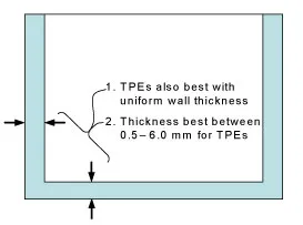
There are a variety of other guidelines for TPE part design that are basically parallel to those used for rigid thermoplastics. Parts mold most consistently where there is a uniform wall thickness. Violating this guideline can result in over packed or under filled sections in the part and likely part warping. Design softer TPE grade parts with 0.25° draft angles and harder TPE grades with 0.5° draft angles to avoid ejection difficulties. Ribs thickness should be 50% of the wall thickness. Similarly, bosses should have a thickness of 50% of the wall. Undercuts of 0.7 mm for harder TPE grades to 2.0 mm for softer TPE grades can be ejected directly without using a special mold design articulation feature to relieve the interference. Typically part wall thicknesses should be limited to the range of 0.5 to 6 mm thick to avoid filling problems or extended cooling requirements. Part corners should have a radius, e.g. 0.5 mm, to avoid the air trap and subsequent burning that can occur.
TPE parts are used in an extremely wide variety of applications and markets. Example TPE parts that are injection molded include the following to cite a few.
- Seals for plumbing
- Vacuum seals
- Oil seals
- O-rings
- Bumpers for appliances, automotive and furniture
- Power transmission / torque coupler
- Mounts
- Sport grips
- Overmolded soft touch surfaces
- Tool handles
- Flexible keypads
- Armor cladding for electronic devices
- Syringe plunger seal
- Connectors
- Electrical plugs
- Strain relief on small electrical appliances
- Tray liners
- Air bag door covers
- Shifter and hand brake grips
- Auto headlamp seals
- Kitchenware
- Eyedropper bulbs
- Drive axle seals
- Appliance motor mounts
Auto Gear Case Seal using EPDM/PP TPV |
TPE injection molded parts are so ubiquitous that there may be very few industries where one cannot find them. The many markets could not all be listed here, but they include:
- Appliances
- Architecture
- Automotive
- Medical
- Hardware
- Houseware
- Electronics
- Trucks
- Industrial equipment
- Hose
- Electrical
- Stationery
- Plumbing
- Sporting goods
- Power transmission
- Irrigation
- Cosmetics
- Electrical
Those who are developing TPE injection molded parts will benefit from an understanding of TPE part design guidelines. There area a number of steps in the part development process that must be included in order to have a successful part. Designing to account for the injection molding process is critical to achieving good parts and to avoid long term processing and part quality issues. Well designed TPE parts will continue to be used more widely in commercial applications as they continue to prove their performance in the rapidly growing TPE market.
Introduction
The thermoplastic elastomers (TPEs) provide good compression recovery and seal force retention. These materials can be deformed and quickly return to nearly the original dimensions and geometry like traditional thermoset rubber materials. TPEs are commercially available with wide variations in performance and so TPE parts can have a full range of performance capabilities and have a range of part economics. While nearly all thermoplastic processes can be used for TPEs, the injection molding process is the most popular judged by the greatest number of parts types made with this process. A good understanding of the steps in designing a TPE part for the
TPE Used For Part
Identifying the correct TPE type and grade to use is the first step to successfully design a part. The general breakdown of TPEs used for injection molding into TPE parts is into the broad categories of block copolymers, rubber-plastic blends and thermoplastic vulcanizates. Block copolymer include styrene block copolymers (SBCs, SBS, SEBS, SIS), thermoplastic urethanes (TPUs) and copolyester block copolymers (COPE) as some of the major ones. Rubber : plastic blends of commercial significance include the EPDM rubber : polypropylene (PP) blends (i.e. thermoplastic olefin blends, TPOs) and the nitrile rubber (NBR) : polyvinylchloride (PVC) blends. Thermoplastic vulcanizates consist of a cross-linked rubber phase dispersed in a continuous thermoplastic phase and these include the rubber : plastic combinations: EPDM : PP (EPDM/PP TPV), Butyl rubber : PP (IIR/PP TPV, Nitrile rubber : PP (NBR/PP TPV), Ethylene acrylate rubber : PET polyester (or nylon) (AEM TPV) and silicone rubber : nylon (or PET) (TPSiV). This step consists of the steps:
- Material selection
- Driving environmental conditions identified
- Material performance extremes contrasted to requirements
- Material selection validated
- Part design process accounts for characteristics of selected TPE
Consult a good TPE information source to guide this part of the process.
Part Design Process
Designing a TPE part for injection molding will include the process steps common for developing a successful part design.The broad breakdown of the design process is into the following steps:
- Part Aesthetics and Differentiation
- Industrial design
- Overall design validated with feedback
Kitchenware EPDM/PP TPV Industrial Design Example |
- Criteria established for part function
- Design to meet functions
- Validate design functions
- Injection molding process design factors
- Mold design capabilities and limits accounted for
- Moldfilling conducted on part design
- Process economics and quality capabilities optimized
- Demolding, assembly and automation optimized
The focus here will be on this last portion of the design process where the injection molding process design factors must be accounted for when designing details for the TPE parts.
Design For Injection Molding
The TPE part designed for injection molding needs to incorporate design features that work within the mold limitations, processing effects and economics associated with this process. Many issues required for rigid thermoplastics are roughly equivalent with TPEs. But since TPEs are softer and often quite flexible there are some factors that can be more forgiving and others that are less forgiving. These differences include:
- Softer TPEs require large ejector pins
- TPEs have higher surface friction with more flexible material
- Deep textures are hard to eject and require larger draft angles, but may not be as difficult as for a rigid thermoplastic
- Short cooling times cause deformation, ejector pin marks since the softer TPE is easier to deform until fully cooled
- Ribs require a slightly higher draft angle
- Poor release draft angles can cause a vacuum and part collapse during ejection can occur easier in TPEs
- Runner systems are very flexible and can hang during ejection
- Flexible TPEs can often be readily ejected even with significant undercuts
- Avoids need for more elaborate mold splits or collapsible cores
- Allows for air ejection in some cases
- For overmolding use softer TPE over rigid plastic substrate to avoid deforming the softer TPE portion, and the TPE grade must be compatible to bond to the plastic
- Gussets to support bosses may be less problematic in the softer TPEs, where the high stress concentration points flex instead of cracking as in rigid thermoplastics
Undercut Design Guidelines for TPEs |
There are some processing options that may be limited to the specific TPE and grade chosen so the raw material supplier should be consulted.
The mold design process and process parameters are also important areas to developing a TPE part design. Mold filling analysis and mold design techniques are used to establish the best gate method and location. The runner system style is also a factor in the gating decisions. Molding cycle conditions, cooling and part warp can be evaluated prior to mold construction with computer mold filling analysis (MFA). Knit and weld line locations can be optimized for the gate location with MFA. Optimized tool vent locations can be established with MFA for TPE part molds. After these steps, typically, a prototype mold is prepared to validate the process and make parts to test.
TPE Wall Thickness Guidelines |
There are a variety of other guidelines for TPE part design that are basically parallel to those used for rigid thermoplastics. Parts mold most consistently where there is a uniform wall thickness. Violating this guideline can result in over packed or under filled sections in the part and likely part warping. Design softer TPE grade parts with 0.25° draft angles and harder TPE grades with 0.5° draft angles to avoid ejection difficulties. Ribs thickness should be 50% of the wall thickness. Similarly, bosses should have a thickness of 50% of the wall. Undercuts of 0.7 mm for harder TPE grades to 2.0 mm for softer TPE grades can be ejected directly without using a special mold design articulation feature to relieve the interference. Typically part wall thicknesses should be limited to the range of 0.5 to 6 mm thick to avoid filling problems or extended cooling requirements. Part corners should have a radius, e.g. 0.5 mm, to avoid the air trap and subsequent burning that can occur.
Part Design Examples in Various Markets & Applications
TPE parts are used in an extremely wide variety of applications and markets. Example TPE parts that are injection molded include the following to cite a few.
- Seals for plumbing
- Vacuum seals
- Oil seals
- O-rings
- Bumpers for appliances, automotive and furniture
- Power transmission / torque coupler
- Mounts
- Sport grips
- Overmolded soft touch surfaces
- Tool handles
- Flexible keypads
- Armor cladding for electronic devices
- Syringe plunger seal
- Connectors
- Electrical plugs
- Strain relief on small electrical appliances
- Tray liners
- Air bag door covers
- Shifter and hand brake grips
- Auto headlamp seals
- Kitchenware
- Eyedropper bulbs
- Drive axle seals
- Appliance motor mounts
Auto Gear Case Seal using EPDM/PP TPV |
TPE injection molded parts are so ubiquitous that there may be very few industries where one cannot find them. The many markets could not all be listed here, but they include:
- Appliances
- Architecture
- Automotive
- Medical
- Hardware
- Houseware
- Electronics
- Trucks
- Industrial equipment
- Hose
- Electrical
- Stationery
- Plumbing
- Sporting goods
- Power transmission
- Irrigation
- Cosmetics
- Electrical
Conclusions
Those who are developing TPE injection molded parts will benefit from an understanding of TPE part design guidelines. There area a number of steps in the part development process that must be included in order to have a successful part. Designing to account for the injection molding process is critical to achieving good parts and to avoid long term processing and part quality issues. Well designed TPE parts will continue to be used more widely in commercial applications as they continue to prove their performance in the rapidly growing TPE market.